Tag Archives: Jennifer Chu

When the rocks sing “I got rhythm”

George Gershwin, along with his brother Ira, wrote jazz standards such as “I got rhythm” in 1930 and, before that, “Fascinating rhythm” in 1924 and both seem à propos in relation to this October 9, 2023 news item on phys.org,

f you could sink through the Earth’s crust, you might hear, with a carefully tuned ear, a cacophany of booms and crackles along the way. The fissures, pores, and defects running through rocks are like strings that resonate when pressed and stressed. And as a team of MIT geologists has found, the rhythm and pace of these sounds can tell you something about the depth and strength of the rocks around you.

The fissures and pores running through rocks, from the Earth’s crust to the liquid mantle, are like channels and cavities through which sound can resonate. Credit: iStock [downloaded from https://news.mit.edu/2023/boom-crackle-pop-earth-crust-sounds-1009]

An October 9, 2023 Massachusetts Institute of Technology news release (also on EurekAlert) by Jennifer Chu, which originated the news item, (word play alert) delves down into the material, Note: A link has been removed,

“If you were listening to the rocks, they would be singing at higher and higher pitches, the deeper you go,” says MIT geologist Matěj Peč. 

Peč and his colleagues are listening to rocks, to see whether any acoustic patterns, or “fingerprints” emerge when subjected to various pressures. In lab studies, they have now shown that samples of marble, when subjected to low pressures, emit low-pitched “booms,” while at higher pressures, the rocks generate an ‘avalanche’ of higher-pitched crackles. 

Peč says these acoustic patterns in rocks can help scientists estimate the types of cracks, fissures, and other defects that the Earth’s crust experiences with depth, which they can then use to identify unstable regions below the surface, where there is potential for earthquakes or eruptions. The team’s results, published in the Proceedings of the National Academy of Sciences, could also help inform surveyors’ efforts to drill for renewable, geothermal energy. 

“If we want to tap these very hot geothermal sources, we will have to learn how to drill into rocks that are in this mixed-mode condition, where they are not purely brittle, but also flow a bit,” says Peč, who is an assistant professor in MIT’s Department of Earth, Atmospheric and Planetary Sciences (EAPS). “But overall, this is fundamental science that can help us understand where the lithosphere is strongest.” 

Peč’s collaborators at MIT are lead author and research scientist Hoagy O. Ghaffari, technical associate Ulrich Mok, graduate student Hilary Chang, and professor emeritus of geophysics Brian Evans. Tushar Mittal, co-author and former EAPS postdoc, is now an assistant professor at Penn State University.

Fracture and flow

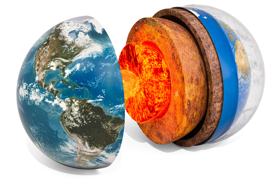
The Earth’s crust is often compared to the skin of an apple. At its thickest, the crust can be 70 kilometers deep — a tiny fraction of the globe’s total, 12,700-kilometer diameter. And yet, the rocks that make up the planet’s thin peel vary greatly in their strength and stability. Geologists infer that rocks near the surface are brittle and fracture easily, compared to rocks at greater depths, where immense pressures, and heat from the core, can make rocks flow. 

The fact that rocks are brittle at the surface and more ductile at depth implies there must be an in-between — a phase in which rocks transition from one to the other, and may have properties of both, able to fracture like granite, and flow like honey. This “brittle-to-ductile transition” is not well understood, though geologists believe it may be where rocks are at their strongest within the crust. 

“This transition state of partly flowing, partly fracturing, is really important, because that’s where we think the peak of the lithosphere’s strength is and where the largest earthquakes nucleate,” Peč says. “But we don’t have a good handle on this type of mixed-mode behavior.”

He and his colleagues are studying how the strength and stability of rocks — whether brittle, ductile, or somewhere in between — varies, based on a rock’s microscopic defects. The size, density, and distribution of defects such as microscopic cracks, fissures, and pores can shape how brittle or ductile a rock can be. 

But measuring the microscopic defects in rocks, under conditions that simulate the Earth’s various pressures and depths, is no trivial task. There is, for instance, no visual-imaging technique that allows scientists to see inside rocks to map their microscopic imperfections. So the team turned to ultrasound, and the idea that, any sound wave traveling through a rock should bounce, vibrate, and reflect off any microscopic cracks and crevices, in specific ways that should reveal something about the pattern of those defects. 

All these defects will also generate their own sounds when they move under stress and therefore both actively sounding through the rock as well as listening to it should give them a great deal of information. They found that the idea should work with ultrasound waves, at megahertz frequencies.

This kind of ultrasound method is analogous to what seismologists do in nature, but at much higher frequencies,” Peč explains. “This helps us to understand the physics that occur at microscopic scales, during the deformation of these rocks.” 

A rock in a hard place

In their experiments, the team tested cylinders of Carrara marble. 

“It’s the same material as what Michaelangelo’s David is made from,” Peč notes. “It’s a very well-characterized material, and we know exactly what it should be doing.”

The team placed each marble cylinder in a a vice-like apparatus made from pistons of aluminum, zirconium, and steel, which together can generate extreme stresses. They placed the vice in a pressurized chamber, then subjected each cylinder to pressures similar to what rocks experience throughout the Earth’s crust.  

As they slowly crushed each rock, the team sent pulses of ultrasound through the top of the sample, and recorded the acoustic pattern that exited through the bottom. When the sensors were not pulsing, they were listening to any naturally occurring acoustic emissions.

They found that at the lower end of the pressure range, where rocks are brittle, the marble indeed formed sudden fractures in response, and the sound waves resembled large, low-frequency booms. At the highest pressures, where rocks are more ductile, the acoustic waves resembled a higher-pitched crackling. The team believes this crackling was produced by microscopic defects called dislocations that then spread and flow like an avalanche. 

“For the first time, we have recorded the ‘noises’ that rocks make when they are deformed across this brittle-to-ductile transition, and we link these noises to the individual microscopic defects that cause them,” Peč says. “We found that these defects massively change their size and propagation velocity as they cross this transition. It’s more complicated than people had thought.”

The team’s characterizations of rocks and their defects at various pressures can help scientists estimate how the Earth’s crust will behave at various depths, such as how rocks might fracture in an earthquake, or flow in an eruption.    

“When rocks are partly fracturing and partly flowing, how does that feed back into the earthquake cycle? And how does that affect the movement of magma through a network of rocks?” Peč says. “Those are larger scale questions that can be tackled with research like this.”

This research was supported, in part, by the National Science Foundation.

Here’s a link to and a citation for the paper,

Microscopic defect dynamics during a brittle-to-ductile transition by Hoagy O’Ghaffari, Matěj Peč, Tushar Mittal, Ulrich Mok, Hilary Chang, and Brian Evans. Proceedings of the National Academy of Sciences 120 (42) e2305667120 DOI: https://doi.org/10.1073/pnas.2305667120 October 9, 2023

This paper is behind a paywall.

400 nm thick glucose fuel cell uses body’s own sugar

This May 12, 2022 news item on Nanowerk reminds me of bioenergy harvesting (using the body’s own processes rather than batteries to power implants),

Glucose is the sugar we absorb from the foods we eat. It is the fuel that powers every cell in our bodies. Could glucose also power tomorrow’s medical implants?

Engineers at MIT [Massachusetts Institute of Technology] and the Technical University of Munich think so. They have designed a new kind of glucose fuel cell that converts glucose directly into electricity. The device is smaller than other proposed glucose fuel cells, measuring just 400 nanometers thick. The sugary power source generates about 43 microwatts per square centimeter of electricity, achieving the highest power density of any glucose fuel cell to date under ambient conditions.

Caption: Silicon chip with 30 individual glucose micro fuel cells, seen as small silver squares inside each gray rectangle. Credit Image: Kent Dayton

A May 12, 2022 MIT news release (also on EuekAlert) by Jennifer Chu, which originated the news item, describes the technology in more detail, Note: A link has been removed,

The new device is also resilient, able to withstand temperatures up to 600 degrees Celsius. If incorporated into a medical implant, the fuel cell could remain stable through the high-temperature sterilization process required for all implantable devices.

The heart of the new device is made from ceramic, a material that retains its electrochemical properties even at high temperatures and miniature scales. The researchers envision the new design could be made into ultrathin films or coatings and wrapped around implants to passively power electronics, using the body’s abundant glucose supply.

“Glucose is everywhere in the body, and the idea is to harvest this readily available energy and use it to power implantable devices,” says Philipp Simons, who developed the design as part of his PhD thesis in MIT’s Department of Materials Science and Engineering (DMSE). “In our work we show a new glucose fuel cell electrochemistry.”

“Instead of using a battery, which can take up 90 percent of an implant’s volume, you could make a device with a thin film, and you’d have a power source with no volumetric footprint,” says Jennifer L.M. Rupp, Simons’ thesis supervisor and a DMSE visiting professor, who is also an associate professor of solid-state electrolyte chemistry at Technical University Munich in Germany.

Simons and his colleagues detail their design today in the journal Advanced Materials. Co-authors of the study include Rupp, Steven Schenk, Marco Gysel, and Lorenz Olbrich.

A “hard” separation

The inspiration for the new fuel cell came in 2016, when Rupp, who specializes in ceramics and electrochemical devices, went to take a routine glucose test toward the end of her pregnancy.

“In the doctor’s office, I was a very bored electrochemist, thinking what you could do with sugar and electrochemistry,” Rupp recalls. “Then I realized, it would be good to have a glucose-powered solid state device. And Philipp and I met over coffee and wrote out on a napkin the first drawings.”

The team is not the first to conceive of a glucose fuel cell, which was initially introduced in the 1960s and showed potential for converting glucose’s chemical energy into electrical energy. But glucose fuel cells at the time were based on soft polymers and were quickly eclipsed by lithium-iodide batteries, which would become the standard power source for medical implants, most notably the cardiac pacemaker.

However, batteries have a limit to how small they can be made, as their design requires the physical capacity to store energy.

“Fuel cells directly convert energy rather than storing it in a device, so you don’t need all that volume that’s required to store energy in a battery,” Rupp says.

In recent years, scientists have taken another look at glucose fuel cells as potentially smaller power sources, fueled directly by the body’s abundant glucose.

A glucose fuel cell’s basic design consists of three layers: a top anode, a middle electrolyte, and a bottom cathode. The anode reacts with glucose in bodily fluids, transforming the sugar into gluconic acid. This electrochemical conversion releases a pair of protons and a pair of electrons. The middle electrolyte acts to separate the protons from the electrons, conducting the protons through the fuel cell, where they combine with air to form molecules of water — a harmless byproduct that flows away with the body’s fluid. Meanwhile, the isolated electrons flow to an external circuit, where they can be used to power an electronic device.

The team looked to improve on existing materials and designs by modifying the electrolyte layer, which is often made from polymers. But polymer properties, along with their ability to conduct protons, easily degrade at high temperatures, are difficult to retain when scaled down to the dimension of nanometers, and are hard to sterilize. The researchers wondered if a ceramic — a heat-resistant material which can naturally conduct protons — could be made into an electrolyte for glucose fuel cells.

“When you think of ceramics for such a glucose fuel cell, they have the advantage of long-term stability, small scalability, and silicon chip integration,” Rupp notes. “They’re hard and robust.”

Peak power

The researchers designed a glucose fuel cell with an electrolyte made from ceria, a ceramic material that possesses high ion conductivity, is mechanically robust, and as such, is widely used as an electrolyte in hydrogen fuel cells. It has also been shown to be biocompatible.

“Ceria is actively studied in the cancer research community,” Simons notes. “It’s also similar to zirconia, which is used in tooth implants, and is biocompatible and safe.”

The team sandwiched the electrolyte with an anode and cathode made of platinum, a stable material that readily reacts with glucose. They fabricated 150 individual glucose fuel cells on a chip, each about 400 nanometers thin, and about 300 micrometers wide (about the width of 30 human hairs). They patterned the cells onto silicon wafers, showing that the devices can be paired with a common semiconductor material. They then measured the current produced by each cell as they flowed a solution of glucose over each wafer in a custom-fabricated test station.

They found many cells produced a peak voltage of about 80 millivolts. Given the tiny size of each cell, this output is the highest power density of any existing glucose fuel cell design.

“Excitingly, we are able to draw power and current that’s sufficient to power implantable devices,” Simons says.

“It is the first time that proton conduction in electroceramic materials can be used for glucose-to-power conversion, defining a new type of electrochemstry,” Rupp says. “It extends the material use-cases from hydrogen fuel cells to new, exciting glucose-conversion modes.”

Here’s a link to and a citation for the paper,

A Ceramic-Electrolyte Glucose Fuel Cell for Implantable Electronics by Philipp Simons, Steven A. Schenk, Marco A. Gysel, Lorenz F. Olbrich, Jennifer L. M. Rupp. Advanced Materials https://doi.org/10.1002/adma.202109075 First published: 05 April 2022

This paper is open access.

A lobster’s stretch and strength in a hydrogel

An MIT team has fabricated a hydrogel-based material that mimics the structure of the lobster’s underbelly, the toughest known hydrogel found in nature. Credits: Courtesy of the researchers

I love this lobster. In most photos, they’re food. This shows off the lobster as a living entity while showcasing its underbelly, which is what this story is all about. From an April 23, 2021 news item on phys.org (Note: A link has been removed),

A lobster’s underbelly is lined with a thin, translucent membrane that is both stretchy and surprisingly tough. This marine under-armor, as MIT [Massachusetts Institute of Technology] engineers reported in 2019, is made from the toughest known hydrogel in nature, which also happens to be highly flexible. This combination of strength and stretch helps shield a lobster as it scrabbles across the seafloor, while also allowing it to flex back and forth to swim.

Now a separate MIT team has fabricated a hydrogel-based material that mimics the structure of the lobster’s underbelly. The researchers ran the material through a battery of stretch and impact tests, and showed that, similar to the lobster underbelly, the synthetic material is remarkably “fatigue-resistant,” able to withstand repeated stretches and strains without tearing.

If the fabrication process could be significantly scaled up, materials made from nanofibrous hydrogels could be used to make stretchy and strong replacement tissues such as artificial tendons and ligaments.

The team’s results are published in the journal Matter. The paper’s MIT co-authors include postdocs Jiahua Ni and Shaoting Lin; graduate students Xinyue Liu and Yuchen Sun; professor of aeronautics and astronautics Raul Radovitzky; professor of chemistry Keith Nelson; mechanical engineering professor Xuanhe Zhao; and former research scientist David Veysset Ph.D. ’16, now at Stanford University; along with Zhao Qin, assistant professor at Syracuse University, and Alex Hsieh of the Army Research Laboratory.

An April 23, 2021 MIT news release (also on EurekAlert) by Jennifer Chu, which originated the news item, offers an overview of the groundwork for this latest research along with technical detail about the latest work,

Nature’s twist

In 2019, Lin and other members of Zhao’s group developed a new kind of fatigue-resistant material made from hydrogel — a gelatin-like class of materials made primarily of water and cross-linked polymers. They fabricated the material from ultrathin fibers of hydrogel, which aligned like many strands of gathered straw when the material was repeatedly stretched. This workout also happened to increase the hydrogel’s fatigue resistance.

“At that moment, we had a feeling nanofibers in hydrogels were important, and hoped to manipulate the fibril structures so that we could optimize fatigue resistance,” says Lin.

In their new study, the researchers combined a number of techniques to create stronger hydrogel nanofibers. The process starts with electrospinning, a fiber production technique that uses electric charges to draw ultrathin threads out of polymer solutions. The team used high-voltage charges to spin nanofibers from a polymer solution, to form a flat film of nanofibers, each measuring about 800 nanometers — a fraction of the diameter of a human hair.

They placed the film in a high-humidity chamber to weld the individual fibers into a sturdy, interconnected network, and then set the film in an incubator to crystallize the individual nanofibers at high temperatures, further strengthening the material.

They tested the film’s fatigue-resistance by placing it in a machine that stretched it repeatedly over tens of thousands of cycles. They also made notches in some films and observed how the cracks propagated as the films were stretched repeatedly. From these tests, they calculated that the nanofibrous films were 50 times more fatigue-resistant than the conventional nanofibrous hydrogels.

Around this time, they read with interest a study by Ming Guo, associate professor of mechanical engineering at MIT, who characterized the mechanical properties of a lobster’s underbelly. This protective membrane is made from thin sheets of chitin, a natural, fibrous material that is similar in makeup to the group’s hydrogel nanofibers.

Guo found that a cross-section of the lobster membrane revealed sheets of chitin stacked at 36-degree angles, similar to twisted plywood, or a spiral staircase. This rotating, layered configuration, known as a bouligand structure, enhanced the membrane’s properties of stretch and strength.

“We learned that this bouligand structure in the lobster underbelly has high mechanical performance, which motivated us to see if we could reproduce such structures in synthetic materials,” Lin says.

Angled architecture

Ni, Lin, and members of Zhao’s group teamed up with Nelson’s lab and Radovitzky’s group in MIT’s Institute for Soldier Nanotechnologies, and Qin’s lab at Syracuse University, to see if they could reproduce the lobster’s bouligand membrane structure using their synthetic, fatigue-resistant films.

“We prepared aligned nanofibers by electrospinning to mimic the chinic fibers existed in the lobster underbelly,” Ni says.

After electrospinning nanofibrous films, the researchers stacked each of five films in successive, 36-degree angles to form a single bouligand structure, which they then welded and crystallized to fortify the material. The final product measured 9 square centimeters and about 30 to 40 microns thick — about the size of a small piece of Scotch tape.

Stretch tests showed that the lobster-inspired material performed similarly to its natural counterpart, able to stretch repeatedly while resisting tears and cracks — a fatigue-resistance Lin attributes to the structure’s angled architecture.

“Intuitively, once a crack in the material propagates through one layer, it’s impeded by adjacent layers, where fibers are aligned at different angles,” Lin explains.

The team also subjected the material to microballistic impact tests with an experiment designed by Nelson’s group. They imaged the material as they shot it with microparticles at high velocity, and measured the particles’ speed before and after tearing through the material. The difference in velocity gave them a direct measurement of the material’s impact resistance, or the amount of energy it can absorb, which turned out to be a surprisingly tough 40 kilojoules per kilogram. This number is measured in the hydrated state.

“That means that a 5-millimeter steel ball launched at 200 meters per second would be arrested by 13 millimeters of the material,” Veysset says. “It is not as resistant as Kevlar, which would require 1 millimeter, but the material beats Kevlar in many other categories.”

It’s no surprise that the new material isn’t as tough as commercial antiballistic materials. It is, however, significantly sturdier than most other nanofibrous hydrogels such as gelatin and synthetic polymers like PVA. The material is also much stretchier than Kevlar. This combination of stretch and strength suggests that, if their fabrication can be sped up, and more films stacked in bouligand structures, nanofibrous hydrogels may serve as flexible and tough artificial tissues.

“For a hydrogel material to be a load-bearing artificial tissue, both strength and deformability are required,” Lin says. “Our material design could achieve these two properties.”

If you have the time and the interest, do check out the April 23, 2021 MIT news release, which features a couple of informative GIFs.

Here’s a link to and a citation for the paper,

Strong fatigue-resistant nanofibrous hydrogels inspired by lobster underbelly by Jiahua Ni, Shaoting Lin, Zhao Qin, David Veysset, Xinyue Liu, Yuchen Sun, Alex J. Hsieh, Raul Radovitzky, Keith A. Nelson, Xuanhe Zhao. Matter, 2021; DOI: 10.1016/j.matt.2021.03.023 Published April 23, 2021

This paper is behind a paywall.

Spooling strips of graphene

An April 18, 2018 news item on phys.org highlights an exciting graphene development at the Massachusetts Institute of Technology (MIT),

MIT engineers have developed a continuous manufacturing process that produces long strips of high-quality graphene.

The team’s results are the first demonstration of an industrial, scalable method for manufacturing high-quality graphene that is tailored for use in membranes that filter a variety of molecules, including salts, larger ions, proteins, or nanoparticles. Such membranes should be useful for desalination, biological separation, and other applications.

A new manufacturing process produces strips of graphene, at large scale, for use in membrane technologies and other applications. Image: Christine Daniloff, MIT

An April 17, 2018 MIT news release (also on EurekAlert) by Jennifer Chu, which originated the news item,. provides more detail,

“For several years, researchers have thought of graphene as a potential route to ultrathin membranes,” says John Hart, associate professor of mechanical engineering and director of the Laboratory for Manufacturing and Productivity at MIT. “We believe this is the first study that has tailored the manufacturing of graphene toward membrane applications, which require the graphene to be seamless, cover the substrate fully, and be of high quality.”

Hart is the senior author on the paper, which appears online in the journal Applied Materials and Interfaces. The study includes first author Piran Kidambi, a former MIT postdoc who is now an assistant professor at Vanderbilt University; MIT graduate students Dhanushkodi Mariappan and Nicholas Dee; Sui Zhang of the National University of Singapore; Andrey Vyatskikh, a former student at the Skolkovo Institute of Science and Technology who is now at Caltech; and Rohit Karnik, an associate professor of mechanical engineering at MIT.

Growing graphene

For many researchers, graphene is ideal for use in filtration membranes. A single sheet of graphene resembles atomically thin chicken wire and is composed of carbon atoms joined in a pattern that makes the material extremely tough and impervious to even the smallest atom, helium.

Researchers, including Karnik’s group, have developed techniques to fabricate graphene membranes and precisely riddle them with tiny holes, or nanopores, the size of which can be tailored to filter out specific molecules. For the most part, scientists synthesize graphene through a process called chemical vapor deposition, in which they first heat a sample of copper foil and then deposit onto it a combination of carbon and other gases.

Graphene-based membranes have mostly been made in small batches in the laboratory, where researchers can carefully control the material’s growth conditions. However, Hart and his colleagues believe that if graphene membranes are ever to be used commercially they will have to be produced in large quantities, at high rates, and with reliable performance.

“We know that for industrialization, it would need to be a continuous process,” Hart says. “You would never be able to make enough by making just pieces. And membranes that are used commercially need to be fairly big – some so big that you would have to send a poster-wide sheet of foil into a furnace to make a membrane.”

A factory roll-out

The researchers set out to build an end-to-end, start-to-finish manufacturing process to make membrane-quality graphene.

The team’s setup combines a roll-to-roll approach – a common industrial approach for continuous processing of thin foils – with the common graphene-fabrication technique of chemical vapor deposition, to manufacture high-quality graphene in large quantities and at a high rate. The system consists of two spools, connected by a conveyor belt that runs through a small furnace. The first spool unfurls a long strip of copper foil, less than 1 centimeter wide. When it enters the furnace, the foil is fed through first one tube and then another, in a “split-zone” design.

While the foil rolls through the first tube, it heats up to a certain ideal temperature, at which point it is ready to roll through the second tube, where the scientists pump in a specified ratio of methane and hydrogen gas, which are deposited onto the heated foil to produce graphene.

“Graphene starts forming in little islands, and then those islands grow together to form a continuous sheet,” Hart says. “By the time it’s out of the oven, the graphene should be fully covering the foil in one layer, kind of like a continuous bed of pizza.”

As the graphene exits the furnace, it’s rolled onto the second spool. The researchers found that they were able to feed the foil continuously through the system, producing high-quality graphene at a rate of 5 centimers per minute. Their longest run lasted almost four hours, during which they produced about 10 meters of continuous graphene.

“If this were in a factory, it would be running 24-7,” Hart says. “You would have big spools of foil feeding through, like a printing press.”

Flexible design

Once the researchers produced graphene using their roll-to-roll method, they unwound the foil from the second spool and cut small samples out. They cast the samples with a polymer mesh, or support, using a method developed by scientists at Harvard University, and subsequently etched away the underlying copper.

“If you don’t support graphene adequately, it will just curl up on itself,” Kidambi says. “So you etch copper out from underneath and have graphene directly supported by a porous polymer – which is basically a membrane.”

The polymer covering contains holes that are larger than graphene’s pores, which Hart says act as microscopic “drumheads,” keeping the graphene sturdy and its tiny pores open.

The researchers performed diffusion tests with the graphene membranes, flowing a solution of water, salts, and other molecules across each membrane. They found that overall, the membranes were able to withstand the flow while filtering out molecules. Their performance was comparable to graphene membranes made using conventional, small-batch approaches.

The team also ran the process at different speeds, with different ratios of methane and hydrogen gas, and characterized the quality of the resulting graphene after each run. They drew up plots to show the relationship between graphene’s quality and the speed and gas ratios of the manufacturing process. Kidambi says that if other designers can build similar setups, they can use the team’s plots to identify the settings they would need to produce a certain quality of graphene.

“The system gives you a great degree of flexibility in terms of what you’d like to tune graphene for, all the way from electronic to membrane applications,” Kidambi says.

Looking forward, Hart says he would like to find ways to include polymer casting and other steps that currently are performed by hand, in the roll-to-roll system.

“In the end-to-end process, we would need to integrate more operations into the manufacturing line,” Hart says. “For now, we’ve demonstrated that this process can be scaled up, and we hope this increases confidence and interest in graphene-based membrane technologies, and provides a pathway to commercialization.”

Here’s a link to and a citation for the paper,

A Scalable Route to Nanoporous Large-Area Atomically Thin Graphene Membranes by Roll-to-Roll Chemical Vapor Deposition and Polymer Support Casting by Piran R. Kidambi, Dhanushkodi D. Mariappan, Nicholas T. Dee, Andrey Vyatskikh, Sui Zhang, Rohit Karnik, and A. John Hart. ACS Appl. Mater. Interfaces, 2018, 10 (12), pp 10369–10378 DOI: 10.1021/acsami.8b00846 Publication Date (Web): March 19, 2018

Copyright © 2018 American Chemical Society

This paper is behind a paywall.

Finally, there is a video of the ‘graphene spooling out’ process,

Tree-on-a-chip

It’s usually organ-on-a-chip or lab-on-a-chip or human-on-a-chip; this is my first tree-on-a-chip.

Engineers have designed a microfluidic device they call a “tree-on-a-chip,” which mimics the pumping mechanism of trees and other plants. Courtesy: MIT

From a March 20, 2017 news item on phys.org,

Trees and other plants, from towering redwoods to diminutive daisies, are nature’s hydraulic pumps. They are constantly pulling water up from their roots to the topmost leaves, and pumping sugars produced by their leaves back down to the roots. This constant stream of nutrients is shuttled through a system of tissues called xylem and phloem, which are packed together in woody, parallel conduits.

Now engineers at MIT [Massachusetts Institute of Technology] and their collaborators have designed a microfluidic device they call a “tree-on-a-chip,” which mimics the pumping mechanism of trees and plants. Like its natural counterparts, the chip operates passively, requiring no moving parts or external pumps. It is able to pump water and sugars through the chip at a steady flow rate for several days. The results are published this week in Nature Plants.

A March 20, 2017 MIT news release by Jennifer Chu, which originated the news item, describes the work in more detail,

Anette “Peko” Hosoi, professor and associate department head for operations in MIT’s Department of Mechanical Engineering, says the chip’s passive pumping may be leveraged as a simple hydraulic actuator for small robots. Engineers have found it difficult and expensive to make tiny, movable parts and pumps to power complex movements in small robots. The team’s new pumping mechanism may enable robots whose motions are propelled by inexpensive, sugar-powered pumps.

“The goal of this work is cheap complexity, like one sees in nature,” Hosoi says. “It’s easy to add another leaf or xylem channel in a tree. In small robotics, everything is hard, from manufacturing, to integration, to actuation. If we could make the building blocks that enable cheap complexity, that would be super exciting. I think these [microfluidic pumps] are a step in that direction.”

Hosoi’s co-authors on the paper are lead author Jean Comtet, a former graduate student in MIT’s Department of Mechanical Engineering; Kaare Jensen of the Technical University of Denmark; and Robert Turgeon and Abraham Stroock, both of Cornell University.

A hydraulic lift

The group’s tree-inspired work grew out of a project on hydraulic robots powered by pumping fluids. Hosoi was interested in designing hydraulic robots at the small scale, that could perform actions similar to much bigger robots like Boston Dynamic’s Big Dog, a four-legged, Saint Bernard-sized robot that runs and jumps over rough terrain, powered by hydraulic actuators.

“For small systems, it’s often expensive to manufacture tiny moving pieces,” Hosoi says. “So we thought, ‘What if we could make a small-scale hydraulic system that could generate large pressures, with no moving parts?’ And then we asked, ‘Does anything do this in nature?’ It turns out that trees do.”

The general understanding among biologists has been that water, propelled by surface tension, travels up a tree’s channels of xylem, then diffuses through a semipermeable membrane and down into channels of phloem that contain sugar and other nutrients.

The more sugar there is in the phloem, the more water flows from xylem to phloem to balance out the sugar-to-water gradient, in a passive process known as osmosis. The resulting water flow flushes nutrients down to the roots. Trees and plants are thought to maintain this pumping process as more water is drawn up from their roots.

“This simple model of xylem and phloem has been well-known for decades,” Hosoi says. “From a qualitative point of view, this makes sense. But when you actually run the numbers, you realize this simple model does not allow for steady flow.”

In fact, engineers have previously attempted to design tree-inspired microfluidic pumps, fabricating parts that mimic xylem and phloem. But they found that these designs quickly stopped pumping within minutes.

It was Hosoi’s student Comtet who identified a third essential part to a tree’s pumping system: its leaves, which produce sugars through photosynthesis. Comtet’s model includes this additional source of sugars that diffuse from the leaves into a plant’s phloem, increasing the sugar-to-water gradient, which in turn maintains a constant osmotic pressure, circulating water and nutrients continuously throughout a tree.

Running on sugar

With Comtet’s hypothesis in mind, Hosoi and her team designed their tree-on-a-chip, a microfluidic pump that mimics a tree’s xylem, phloem, and most importantly, its sugar-producing leaves.

To make the chip, the researchers sandwiched together two plastic slides, through which they drilled small channels to represent xylem and phloem. They filled the xylem channel with water, and the phloem channel with water and sugar, then separated the two slides with a semipermeable material to mimic the membrane between xylem and phloem. They placed another membrane over the slide containing the phloem channel, and set a sugar cube on top to represent the additional source of sugar diffusing from a tree’s leaves into the phloem. They hooked the chip up to a tube, which fed water from a tank into the chip.

With this simple setup, the chip was able to passively pump water from the tank through the chip and out into a beaker, at a constant flow rate for several days, as opposed to previous designs that only pumped for several minutes.

“As soon as we put this sugar source in, we had it running for days at a steady state,” Hosoi says. “That’s exactly what we need. We want a device we can actually put in a robot.”

Hosoi envisions that the tree-on-a-chip pump may be built into a small robot to produce hydraulically powered motions, without requiring active pumps or parts.

“If you design your robot in a smart way, you could absolutely stick a sugar cube on it and let it go,” Hosoi says.

This research was supported, in part, by the Defense Advance Research Projects Agency [DARPA].

This research’s funding connection to DARPA reminded me that MIT has an Institute of Soldier Nanotechnologies.

Getting back to the tree-on-a-chip, here’s a link to and a citation for the paper,

Passive phloem loading and long-distance transport in a synthetic tree-on-a-chip by Jean Comtet, Kaare H. Jensen, Robert Turgeon, Abraham D. Stroock & A. E. Hosoi. Nature Plants 3, Article number: 17032 (2017)  doi:10.1038/nplants.2017.32 Published online: 20 March 2017

This paper is behind a paywall.

Entangling thousands of atoms

Quantum entanglement as an idea seems extraordinary to me like something from of the fevered imagination made possible only with certain kinds of hallucinogens. I suppose you could call theoretical physicists who’ve conceptualized entanglement a different breed as they don’t seem to need chemical assistance for their flights of fancy, which turn out to be reality. Researchers at MIT (Massachusetts Institute of Technology) and the University of Belgrade (Serbia) have entangled thousands of atoms with a single photon according to a March 26, 2015 news item on Nanotechnology Now,

Physicists from MIT and the University of Belgrade have developed a new technique that can successfully entangle 3,000 atoms using only a single photon. The results, published today in the journal Nature, represent the largest number of particles that have ever been mutually entangled experimentally.

The researchers say the technique provides a realistic method to generate large ensembles of entangled atoms, which are key components for realizing more-precise atomic clocks.

“You can make the argument that a single photon cannot possibly change the state of 3,000 atoms, but this one photon does — it builds up correlations that you didn’t have before,” says Vladan Vuletic, the Lester Wolfe Professor in MIT’s Department of Physics, and the paper’s senior author. “We have basically opened up a new class of entangled states we can make, but there are many more new classes to be explored.”

A March 26, 2015 MIT news release by Jennifer Chu (also on EurekAlert but dated March 25, 2015), which originated the news item, describes entanglement with particular attention to how it relates to atomic timekeeping,

Entanglement is a curious phenomenon: As the theory goes, two or more particles may be correlated in such a way that any change to one will simultaneously change the other, no matter how far apart they may be. For instance, if one atom in an entangled pair were somehow made to spin clockwise, the other atom would instantly be known to spin counterclockwise, even though the two may be physically separated by thousands of miles.

The phenomenon of entanglement, which physicist Albert Einstein once famously dismissed as “spooky action at a distance,” is described not by the laws of classical physics, but by quantum mechanics, which explains the interactions of particles at the nanoscale. At such minuscule scales, particles such as atoms are known to behave differently from matter at the macroscale.

Scientists have been searching for ways to entangle not just pairs, but large numbers of atoms; such ensembles could be the basis for powerful quantum computers and more-precise atomic clocks. The latter is a motivation for Vuletic’s group.

Today’s best atomic clocks are based on the natural oscillations within a cloud of trapped atoms. As the atoms oscillate, they act as a pendulum, keeping steady time. A laser beam within the clock, directed through the cloud of atoms, can detect the atoms’ vibrations, which ultimately determine the length of a single second.

“Today’s clocks are really amazing,” Vuletic says. “They would be less than a minute off if they ran since the Big Bang — that’s the stability of the best clocks that exist today. We’re hoping to get even further.”

The accuracy of atomic clocks improves as more and more atoms oscillate in a cloud. Conventional atomic clocks’ precision is proportional to the square root of the number of atoms: For example, a clock with nine times more atoms would only be three times as accurate. If these same atoms were entangled, a clock’s precision could be directly proportional to the number of atoms — in this case, nine times as accurate. The larger the number of entangled particles, then, the better an atomic clock’s timekeeping.

It seems weak lasers make big entanglements possible (from the news release),

Scientists have so far been able to entangle large groups of atoms, although most attempts have only generated entanglement between pairs in a group. Only one team has successfully entangled 100 atoms — the largest mutual entanglement to date, and only a small fraction of the whole atomic ensemble.

Now Vuletic and his colleagues have successfully created a mutual entanglement among 3,000 atoms, virtually all the atoms in the ensemble, using very weak laser light — down to pulses containing a single photon. The weaker the light, the better, Vuletic says, as it is less likely to disrupt the cloud. “The system remains in a relatively clean quantum state,” he says.

The researchers first cooled a cloud of atoms, then trapped them in a laser trap, and sent a weak laser pulse through the cloud. They then set up a detector to look for a particular photon within the beam. Vuletic reasoned that if a photon has passed through the atom cloud without event, its polarization, or direction of oscillation, would remain the same. If, however, a photon has interacted with the atoms, its polarization rotates just slightly — a sign that it was affected by quantum “noise” in the ensemble of spinning atoms, with the noise being the difference in the number of atoms spinning clockwise and counterclockwise.

“Every now and then, we observe an outgoing photon whose electric field oscillates in a direction perpendicular to that of the incoming photons,” Vuletic says. “When we detect such a photon, we know that must have been caused by the atomic ensemble, and surprisingly enough, that detection generates a very strongly entangled state of the atoms.”

Vuletic and his colleagues are currently using the single-photon detection technique to build a state-of-the-art atomic clock that they hope will overcome what’s known as the “standard quantum limit” — a limit to how accurate measurements can be in quantum systems. Vuletic says the group’s current setup may be a step toward developing even more complex entangled states.

“This particular state can improve atomic clocks by a factor of two,” Vuletic says. “We’re striving toward making even more complicated states that can go further.”

This research was supported in part by the National Science Foundation, the Defense Advanced Research Projects Agency, and the Air Force Office of Scientific Research.

Here’s a link to and a citation for the paper,

Entanglement with negative Wigner function of almost 3,000 atoms heralded by one photon by Robert McConnell, Hao Zhang, Jiazhong Hu, Senka Ćuk & Vladan Vuletić. Nature 519 439–442 (26 March 2015) doi:10.1038/nature14293 Published online 25 March 2015

This article is behind a paywall but there is a free preview via ReadCube Access.

This image illustrates the entanglement of a large number of atoms. The atoms, shown in purple, are shown mutually entangled with one another. Image: Christine Daniloff/MIT and Jose-Luis Olivares/MIT

This image illustrates the entanglement of a large number of atoms. The atoms, shown in purple, are shown mutually entangled with one another.
Image: Christine Daniloff/MIT and Jose-Luis Olivares/MIT

Batteries made of wood and the mechanical properties of plants

According to Ariel Schwartz in an Aug. 14, 2012 (?) article for Fast Company’s Co.Exist website, batteries made from wood waste may be in our future (Note: I have removed a link),

Researchers from Poznan University of Technology in Poland and Linköping University in Sweden have figured out how to combine lignin with polypyrrole (a conductive polymer) to create a battery cathode that could one day be used in energy storage. The lignin acts as an insulator, while the polypyrrole holds an electric charge.

The discovery is a potential boon for the renewable energy world. As the researchers explain in the journal Science, “Widespread application of electrical power storage may require more abundant materials than those available in inorganics (which often require rare metals), and at a lower cost. Materials for charge storage are desired from easily accessible and renewable sources. Combining cellulose materials and conjugated polymers for charge storage has … attracted attention.”

For anyone (like me) who’s heard the word lignin but doesn’t know the precise meaning, here’s a definition from a Wikipedia essay (Note: I have removed links and footnotes),

Lignin or lignen is a complex chemical compound most commonly derived from wood, and an integral part of the secondary cell walls of plants and some algae. The term was introduced in 1819 by de Candolle and is derived from the Latin word lignum, meaning wood. It is one of the most abundant organic polymers on Earth, exceeded only by cellulose, employing 30% of non-fossil organic carbon, and constituting from a quarter to a third of the dry mass of wood.

This next item also mentions lignin but in reference to mechanical properties that engineers are observing in plant cells.  From the Aug. 14, 2012 news item on Nanowerk,

From an engineer’s perspective, plants such as palm trees, bamboo, maples and even potatoes are examples of precise engineering on a microscopic scale. Like wooden beams reinforcing a house, cell walls make up the structural supports of all plants. Depending on how the cell walls are arranged, and what they are made of, a plant can be as flimsy as a reed, or as sturdy as an oak.

An MIT researcher has compiled data on the microstructures of a number of different plants, from apples and potatoes to willow and spruce trees, and has found that plants exhibit an enormous range of mechanical properties, depending on the arrangement of a cell wall’s four main building blocks: cellulose, hemicellulose, lignin and pectin.

The news item was originated at the Massachusetts Institute of Technology (MIT) by Jennifer Chu’s Aug. 14, 2012 news release,

Lorna Gibson, the [researcher] at MIT, says understanding plants’ microscopic organization may help engineers design new, bio-inspired materials.

“If you look at engineering materials, we have lots of different types, thousands of materials that have more or less the same range of properties as plants,” Gibson says. “But here the plants are, doing it arranging just four basic constituents. So maybe there’s something you can learn about the design of engineered materials.”

A paper detailing Gibson’s findings has been published this month [freely accessible] in the Journal of the Royal Society Interface.

To Gibson, a cell wall’s components bear a close resemblance to certain manmade materials. For example, cellulose, hemicellulose and lignin can be as stiff and strong as manufactured polymers. A plant’s cellular arrangement can also have engineering parallels: cells in woods, for instance, are aligned, similar to engineering honeycombs, while polyhedral cell configurations, such as those found in apples, resemble some industrial foams.

To explore plants’ natural mechanics, Gibson focused on three main plant materials: woods, such as cedar and oak; parenchyma cells, which are found in fruits and root vegetables; and arborescent palm stems, such as coconut trees. She compiled data from her own and other groups’ experiments and analyzed two main mechanical properties in each plant: stiffness and strength.

Among all plants, Gibson observed wide variety in both properties. Fruits and vegetables such as apples and potatoes were the least stiff, while the densest palms were 100,000 times stiffer. Likewise, apples and potatoes fell on the lower end of the strength scale, while palms were 1,000 times stronger.

“There are plants with properties over that whole range,” Gibson says. “So it’s not like potatoes are down here, and wood is over there, and there’s nothing in between. There are plants with properties spanning that whole huge range. And it’s interesting how the plants do that.”

Since I’m always interested in trees, from Chu’s news release,

In trees such as maples and oaks, cells grow and multiply in the cambium layer, just below the bark, increasing the diameter of the trees. The cell walls in wood are composed of a primary layer with cellulose fibers randomly spread throughout it. Three secondary layers lie underneath, each with varying compositions of lignin and cellulose that wind helically through each layer.

Taken together, the cell walls occupy a large portion of a cell, providing structural support. The cells in woods are organized in a honeycomb pattern — a geometric arrangement that gives wood its stiffness and strength.

Parenchyma cells, found in fruits and root vegetables, are much less stiff and strong than wood. The cell walls of apples, potatoes and carrots are much thinner than in wood cells, and made up of only one layer. Cellulose fibers run randomly throughout this layer, reinforcing a matrix of hemicellulose and pectin. Parenchyma cells have no lignin; combined with their thin walls and the random arrangement of their cellulose fibers, Gibson says, this may explain their cell walls’ low stiffness. The cells in each plant are densely packed together, similar to industrial foams used in mattresses and packaging.

Unlike woody trees that grow in diameter over time, the stems of arborescent palms such as coconut trees maintain similar diameters throughout their lifetimes. Instead, as the stem grows taller, palms support this extra weight by increasing the thickness of their cell walls. A cell wall’s thickness depends on where it is along a given palm stem: Cell walls are thicker at the base and periphery of stems, where bending stresses are greatest.

There’s even a nanotechnology slant to this story, from Chu’s news release,

Gibson sees plant mechanics as a valuable resource for engineers designing new materials. For instance, she says, researchers have developed a wide array of materials, from soft elastomers to stiff, strong alloys. Carbon nanotubes have been used to reinforce composite materials, and engineers have made honeycomb-patterned materials with cells as small as a few millimeters wide. But researchers have been unable to fabricate cellular composite materials with the level of control that plants have perfected.

“Plants are multifunctional,” Gibson says. “They have to satisfy a number of requirements: mechanical ones, but also growth, surface area for sunlight and transport of fluids. The microstructures plants have developed satisfy all these requirements. With the development of nanotechnology, I think there is potential to develop multifunctional engineering materials inspired by plant microstructures.”

Given the problems with the forestry sector, these developments (wooden batteries and engineering materials inspired by plant cell walls) should excite some interest.